final project
Inspiration
The Zoetrope
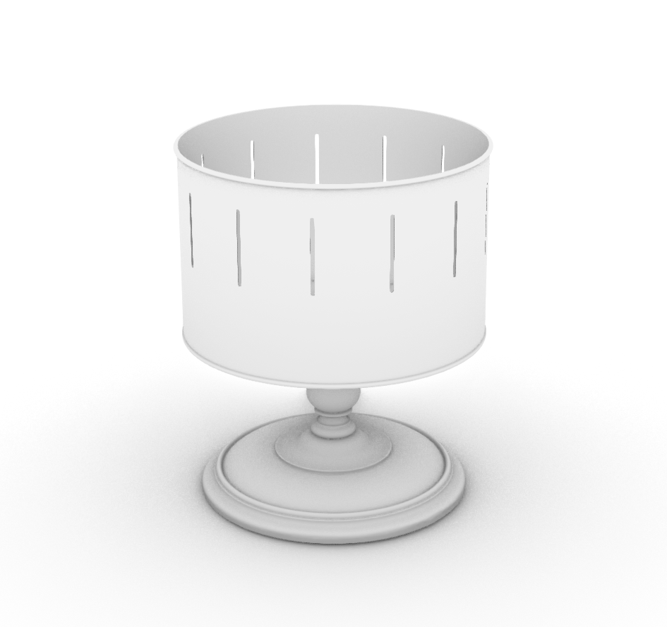
A zoetrope is a pre-film animation device that produces the illusion of motion by displaying a sequence of drawings or photographs showing progressive phases of that motion. It consists of a cylinder with slits cut vertically in the sides. On the inner surface of the cylinder is a band with images from a set of sequenced pictures. As the cylinder spins, the viewer looks through the slits at the pictures across. The slits keep the pictures from blurring together, and the viewer sees a rapid succession of images, creating the illusion of motion.

The zoetrope inspires me because it is not only a device for creating moving images, but also a powerful tool for storytelling. What fascinates me is that the narrative does not rely on a single image, but on the relationship between figures, colors, and the speed at which those figures change. Movement emerges from repetition and variation, and meaning is created through rhythm and sequence rather than through linear description. In this way, the zoetrope becomes less about the individual frames and more about the system that holds them together.
If the figures inside a zoetrope are changed or substituted with something entirely different, the story itself transforms, even though the underlying mechanism remains the same. The narration tool stays constant, but the content reshapes the message. This separation between structure and narrative is especially interesting to me, because it suggests that storytelling can be modular, flexible, and open-ended. The same tool can carry multiple stories, moods, and interpretations depending on how it is used.
For me, this class represents an opportunity to design such a tool, one that tells stories through its own visual language. Rather than focusing on a single outcome, I am interested in creating a system that enables expression through painting and motion. Painting has always been an important medium for me, and I am drawn to processes that are immediate, physical, and expressive. The spray can, in particular, offers a direct and gestural way of working with color and form.
The closest reference I see between the zoetrope and the spray can is the use of stencils. Stencils allow repetition with variation, much like the frames of a zoetrope. They preserve structure while enabling change, making them a bridge between mechanical narration and expressive mark-making. Through this connection, I see the potential to merge motion, painting, and storytelling into a single narrative tool.
Sketches and Diagrams
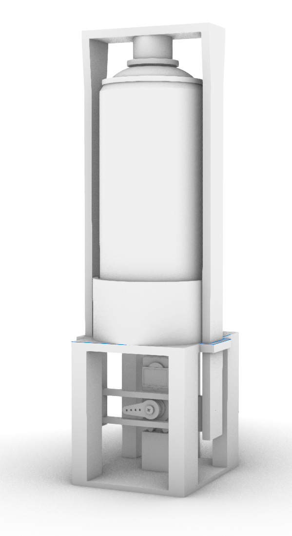
After reflecting on the masks and the rotation mechanism for the machine I want to build, I began creating more precise 3D models to bring the idea closer to reality. These models allowed me to visualize how the components would fit and interact, refine proportions, and anticipate potential issues. This stage was essential for translating conceptual ideas into practical designs, ensuring that th e final construction would be both functional and aligned with my original vision.
Model making process
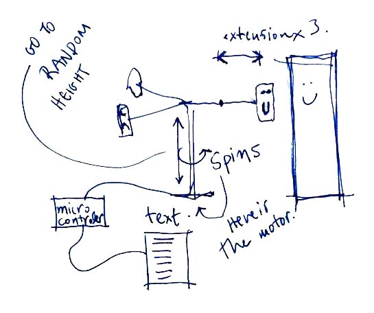
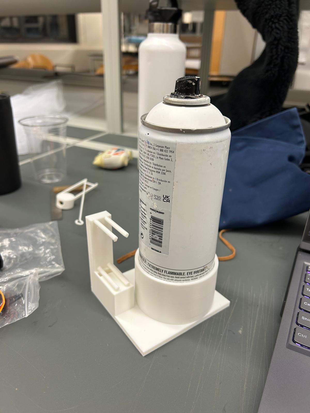
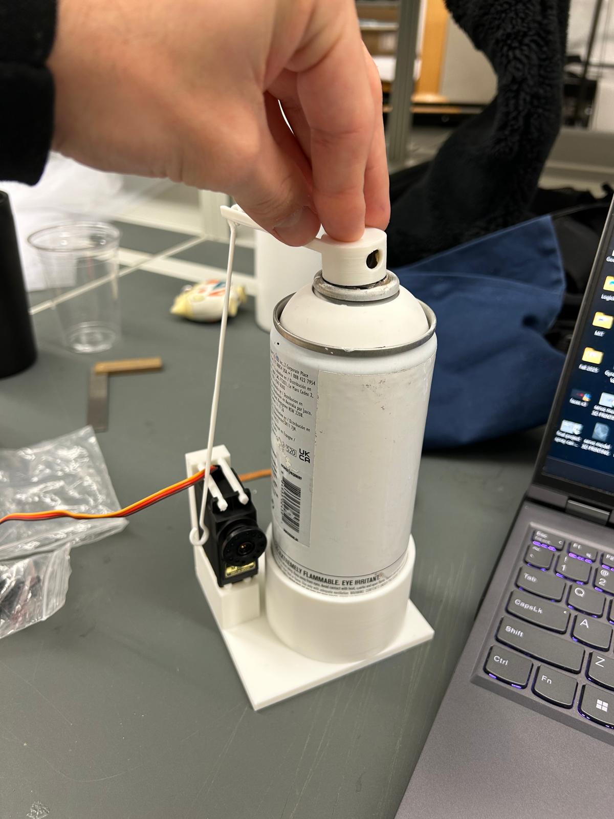
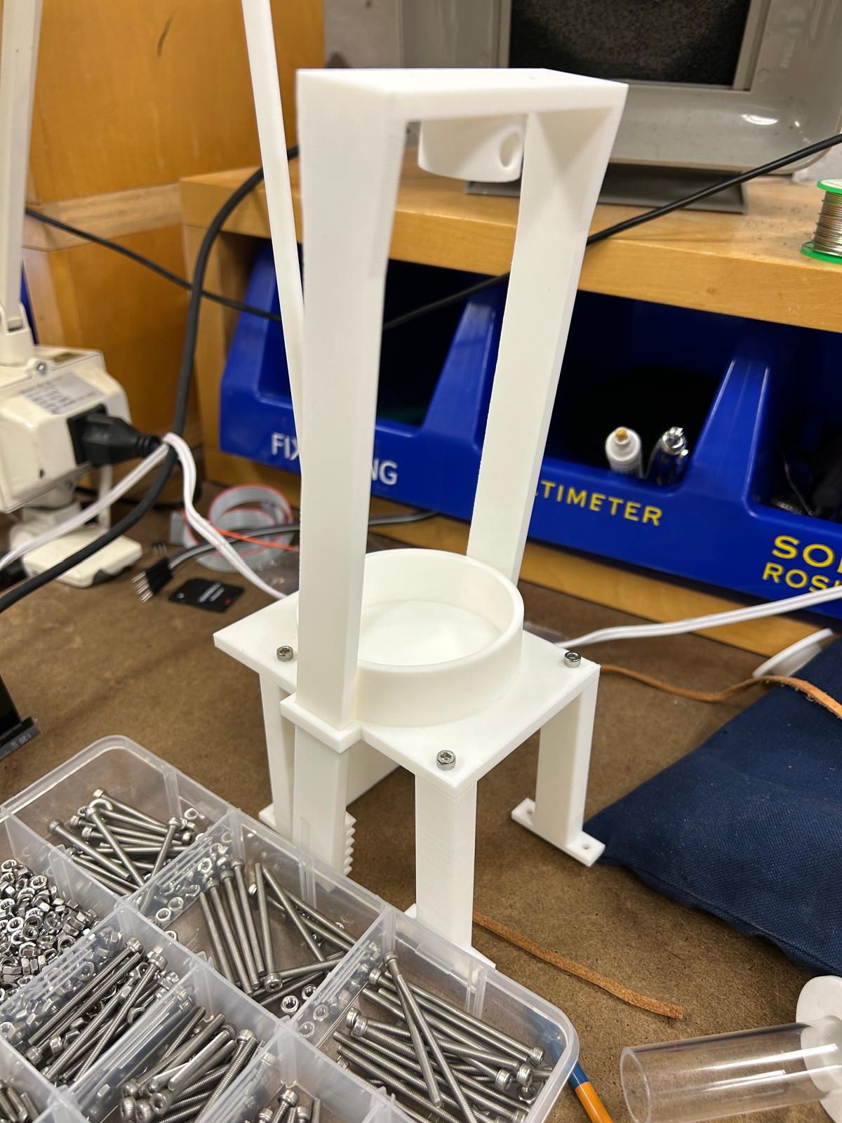
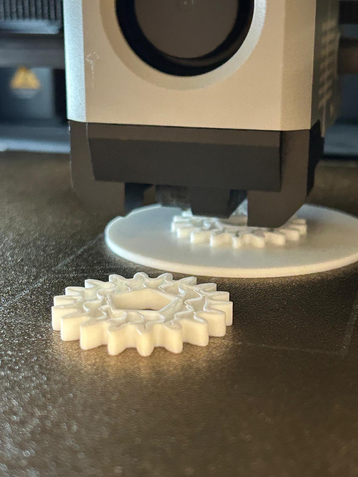
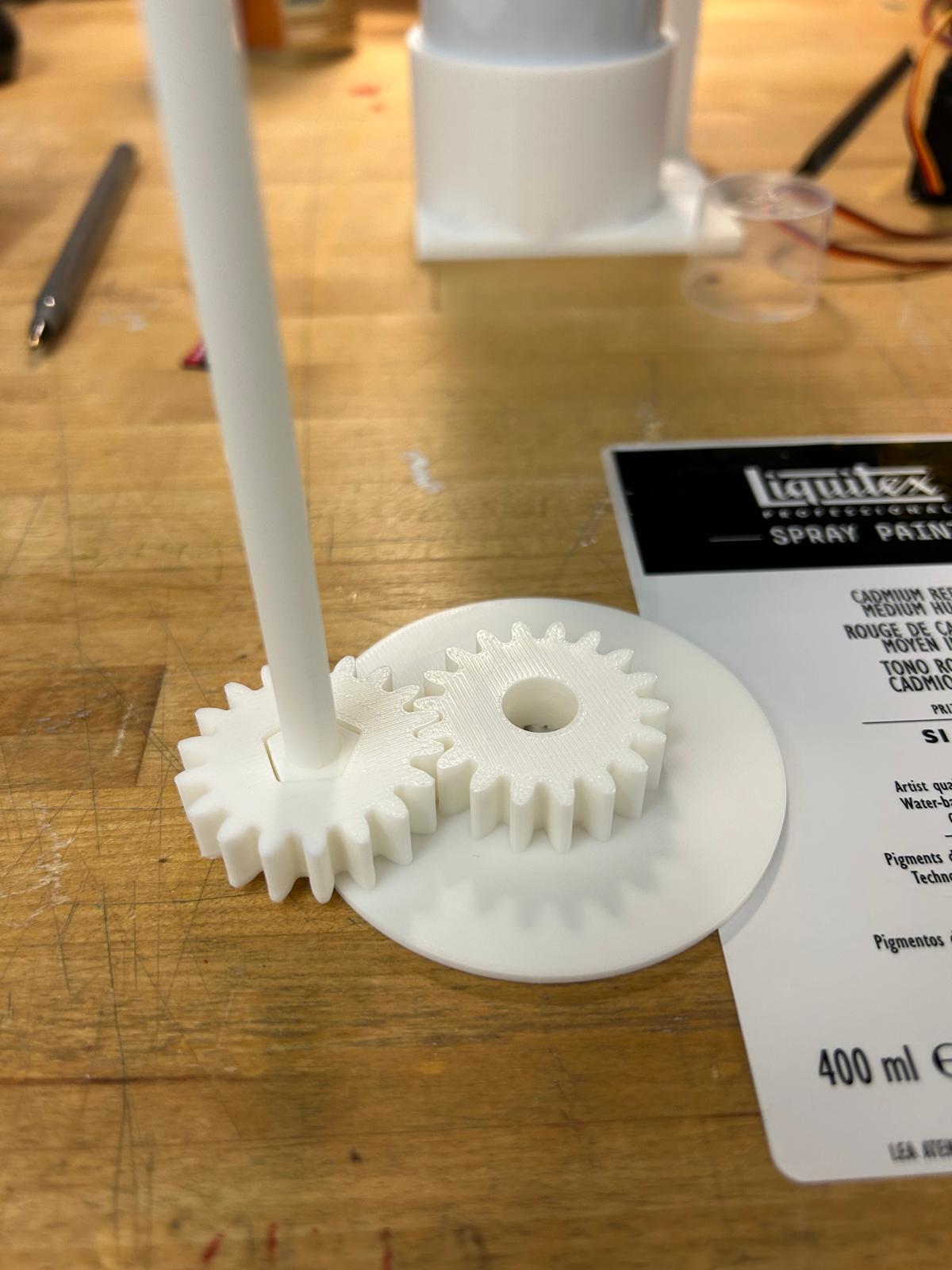
I started creating models to understand how the mechanism would move and trigger the spray can tip to release color. Designing the parts allowed me to visualize the motion and ensure proper alignment for smooth operation. I 3D printed the components and included a dedicated spot for the servo motor, ensuring it would remain stable while moving. This setup helped me test the interaction between the servo, mechanism, and spray can, allowing for precise and controlled color release.
Next Steps and Timeline
Timeline:
• Week 13: Finalize design and gather materials
• Week 14: Build the mechanical structure and integrate servos
• Week 15: Program the control system and test spray patterns
Finalized design
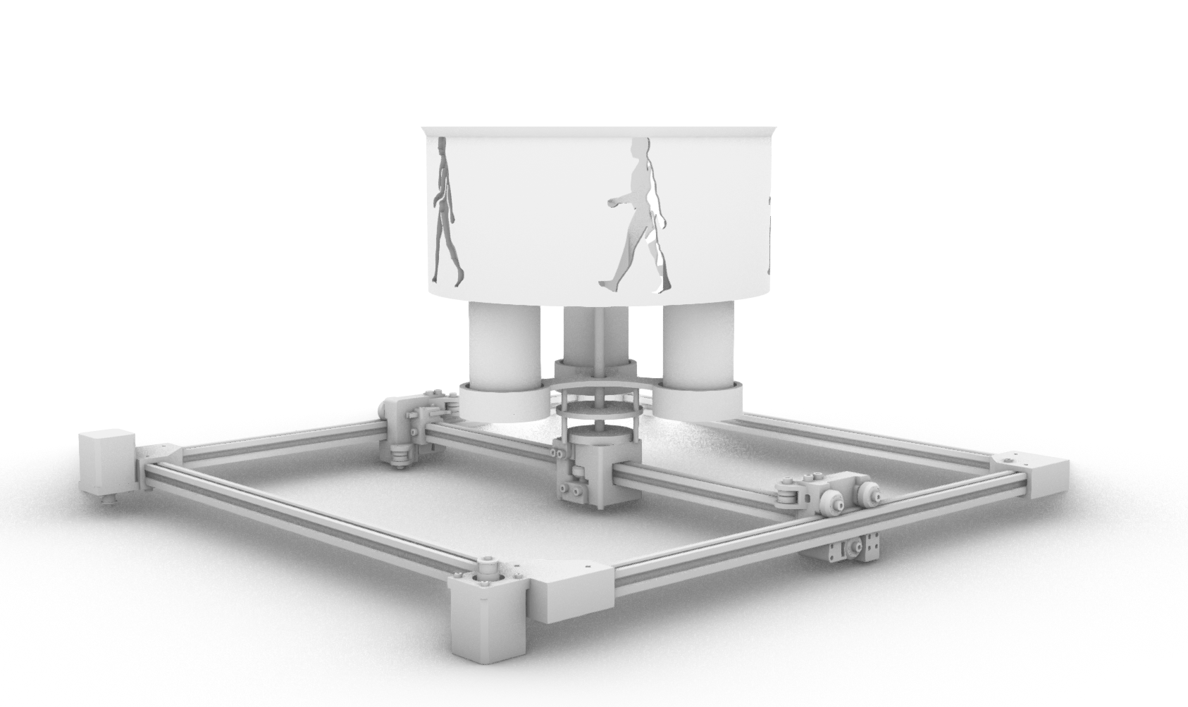
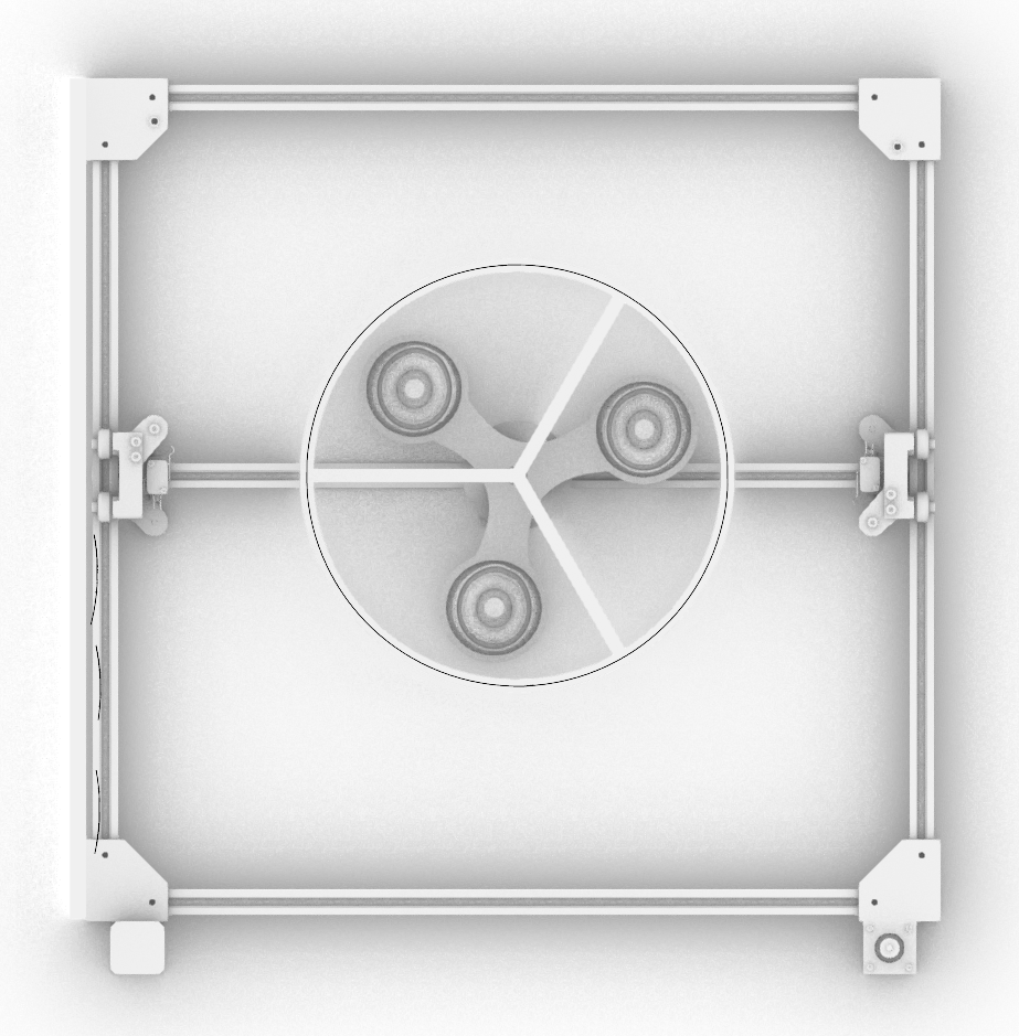
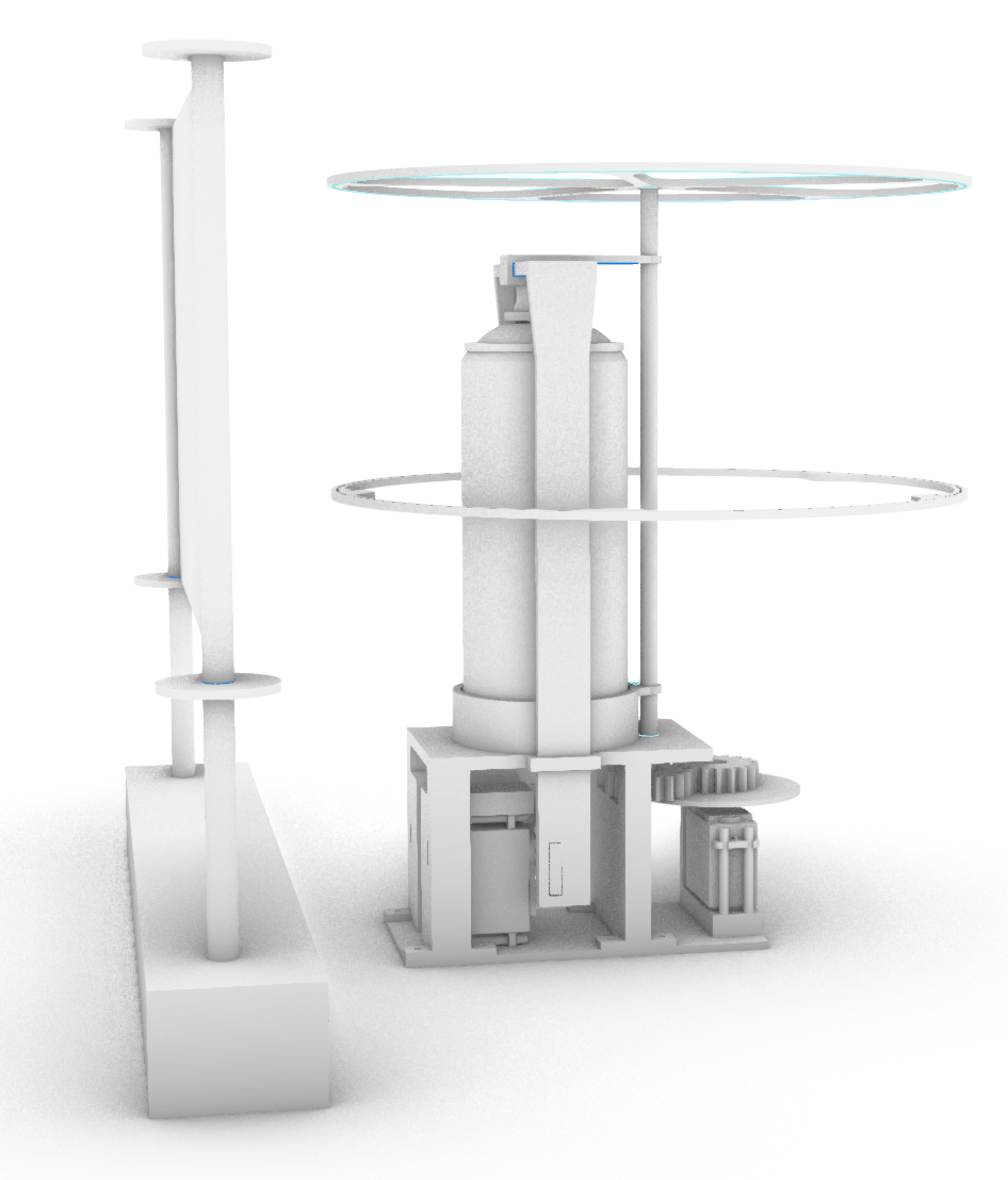
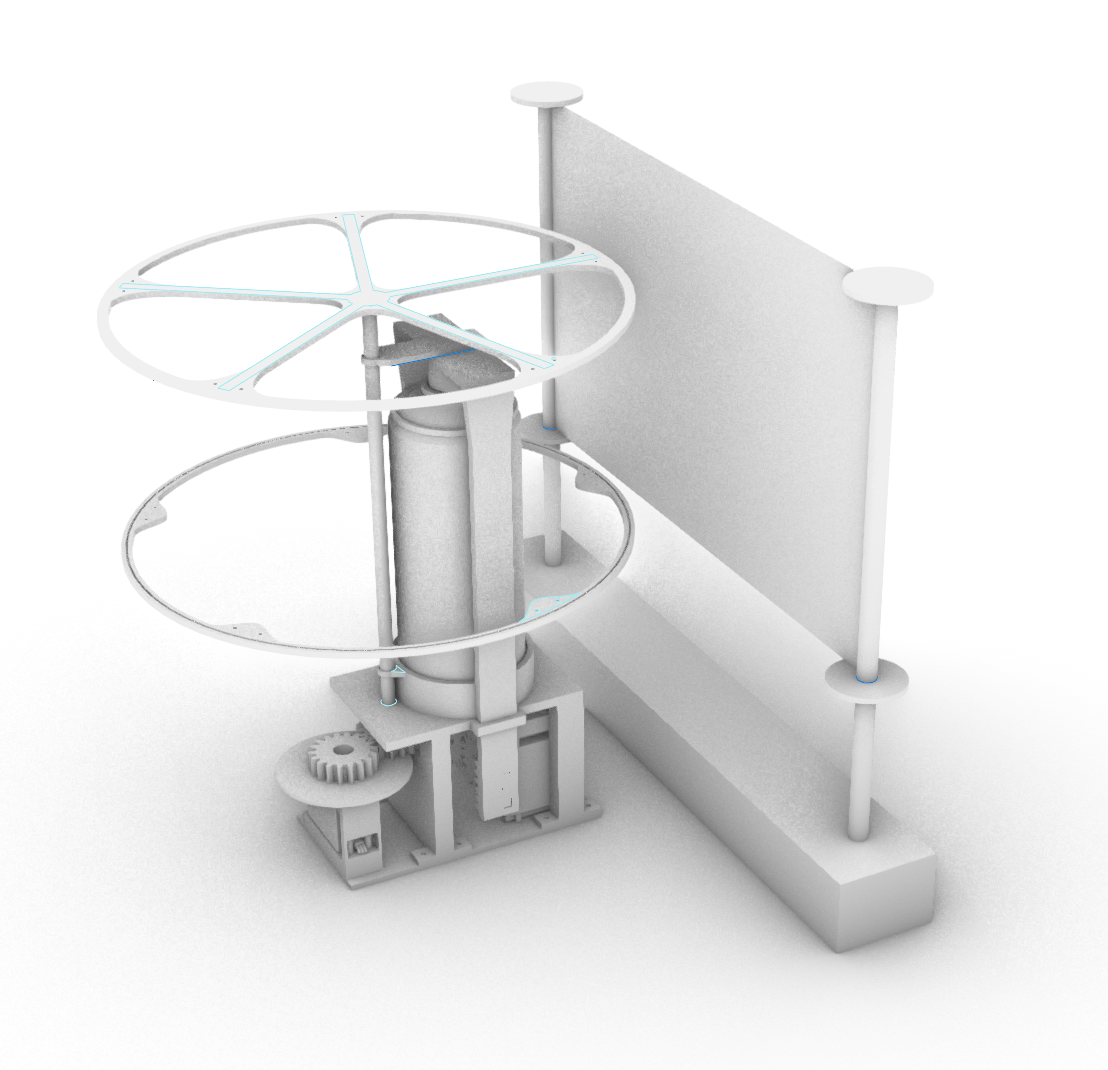
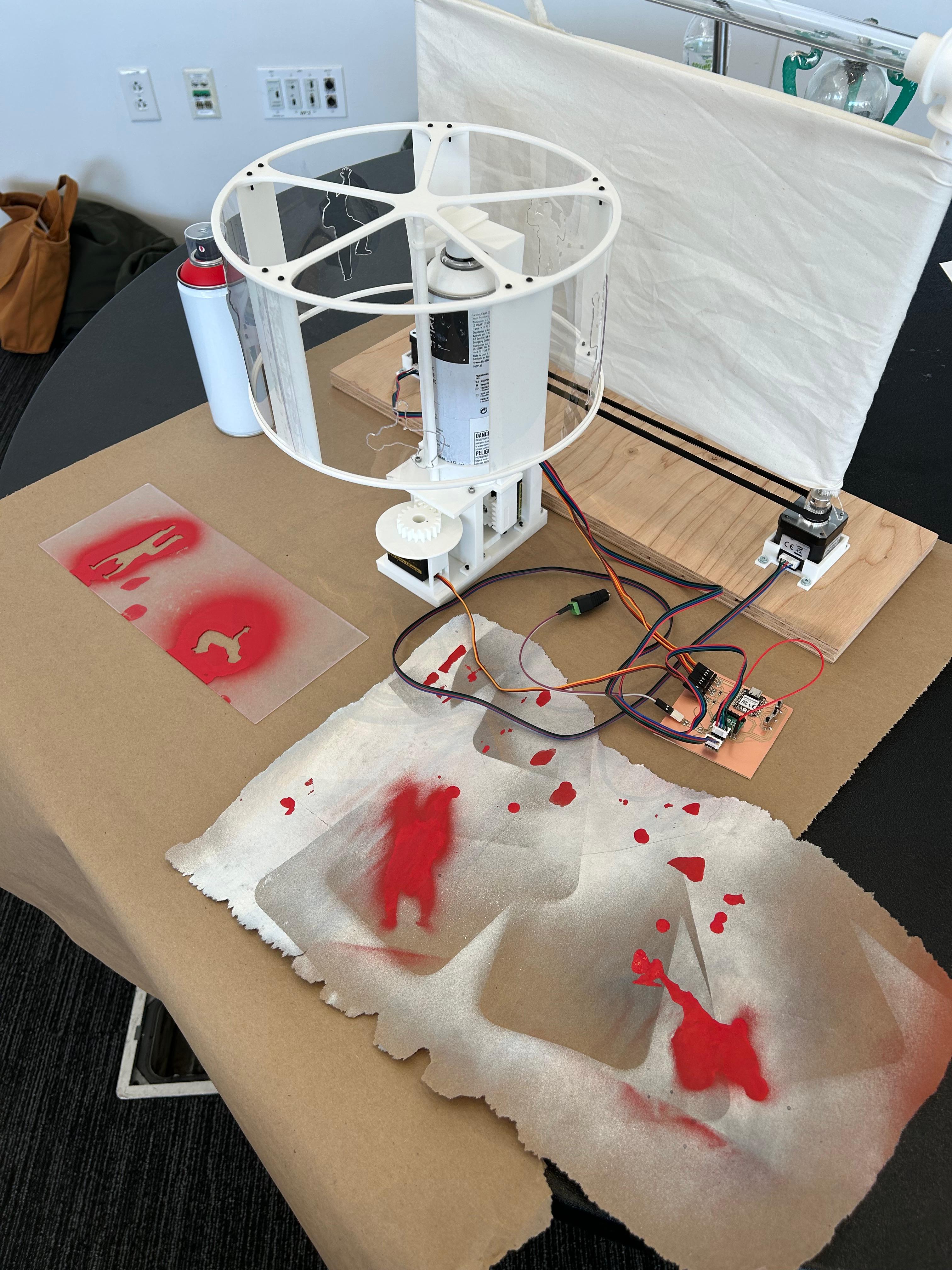
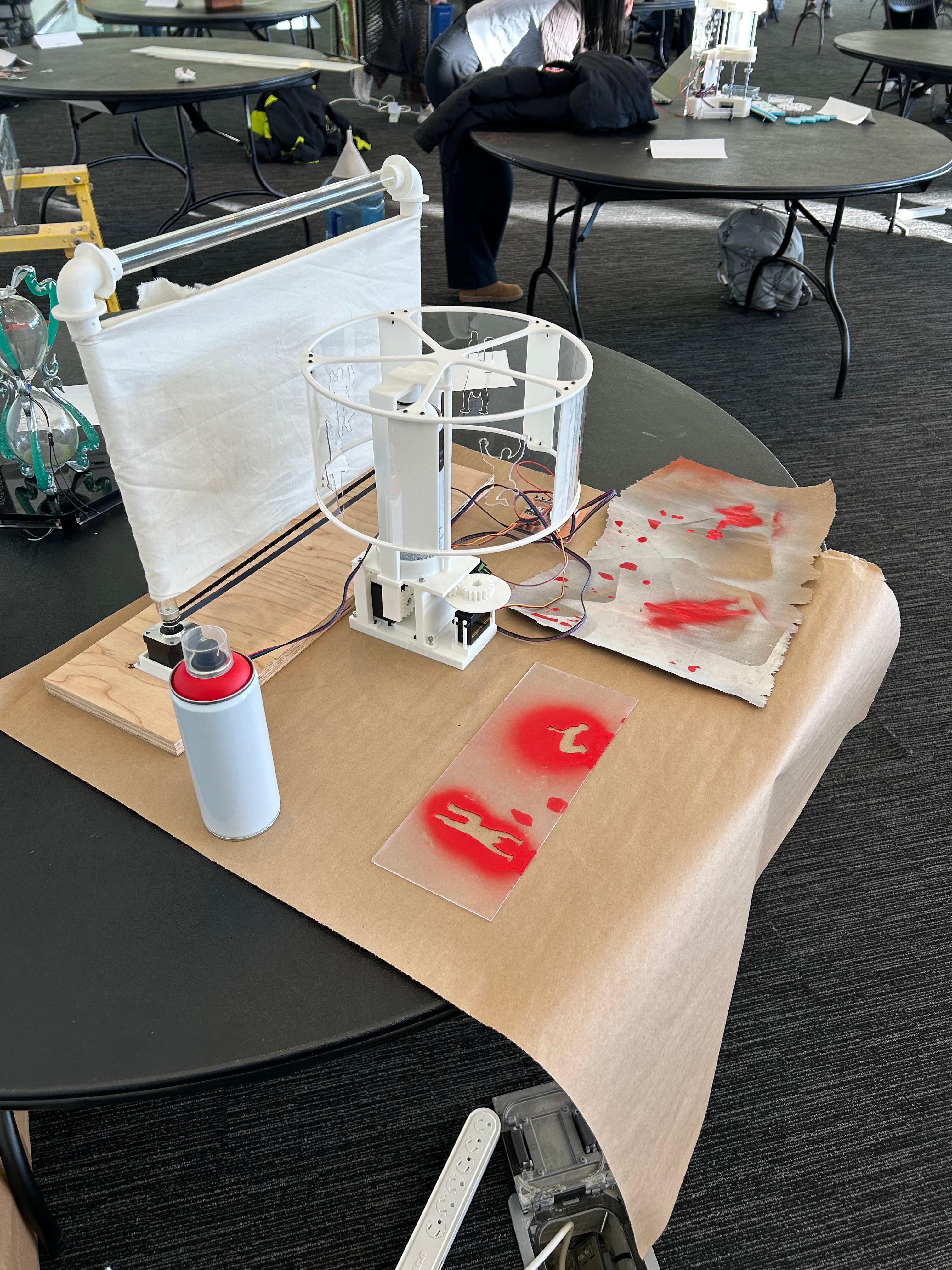
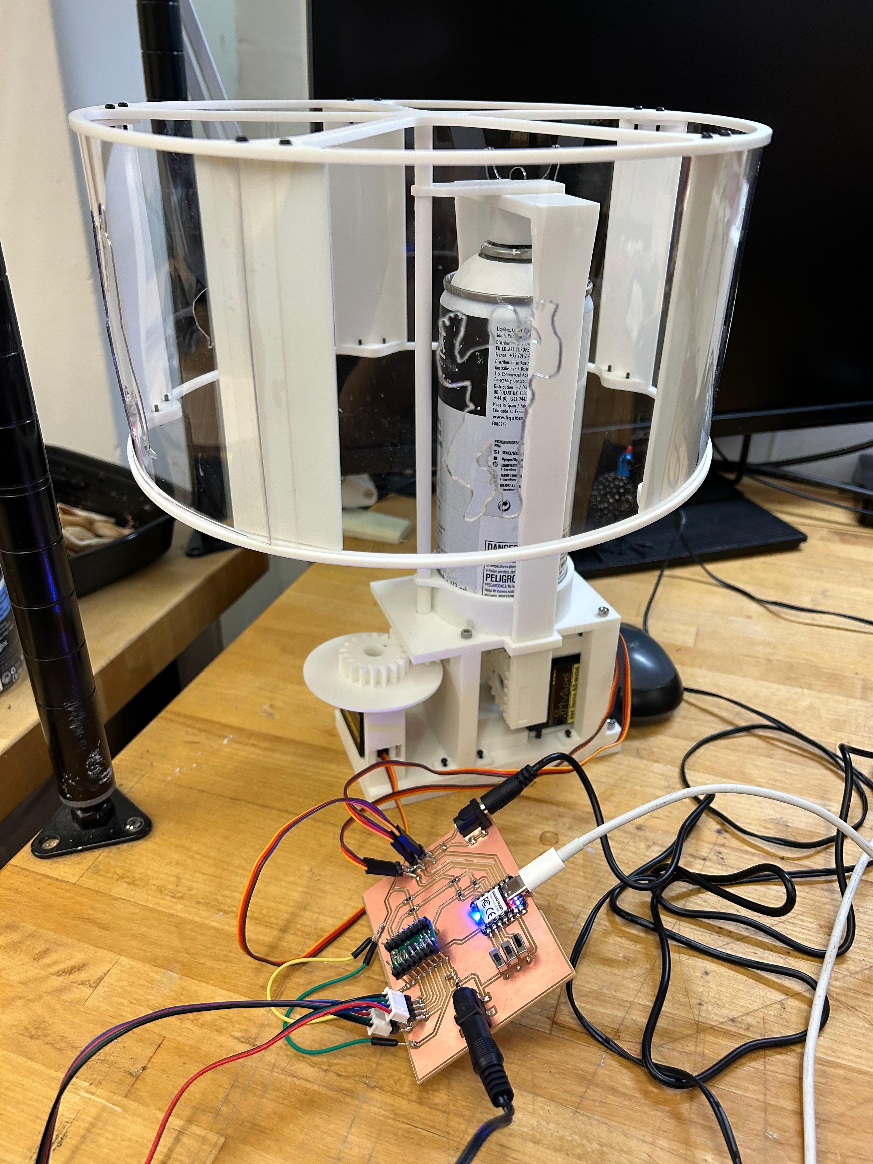
The spray-can machine is a mechanical system designed to produce controlled patterns on a surface through the movement of spray cans. It functions as both a tool and an interface, allowing exploration of the relationship between motion, spatial orientation, and visual outcome. The machine is constructed to rotate and pivot a spray can, coordinating its trajectory to create layered compositions on a canvas or fabric surface. Its design emphasizes precision and repeatability, while still enabling variation through adjustments in speed, angle, and timing. This system encourages interaction and observation, as viewers can engage with the patterns emerging from the machine’s activity. By making the components visible, the machine demonstrates how movement, force, and alignment generate specific visual results. Observers are able to follow the mechanisms in real time, gaining insight into the translation from mechanical motion to painted form.
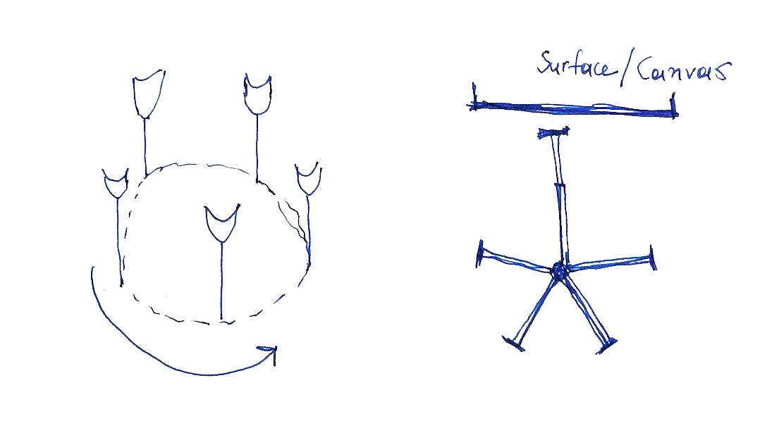
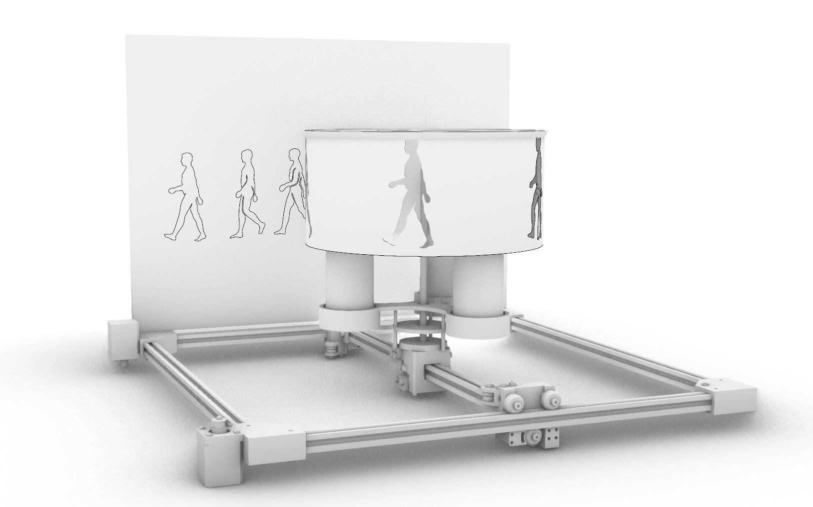
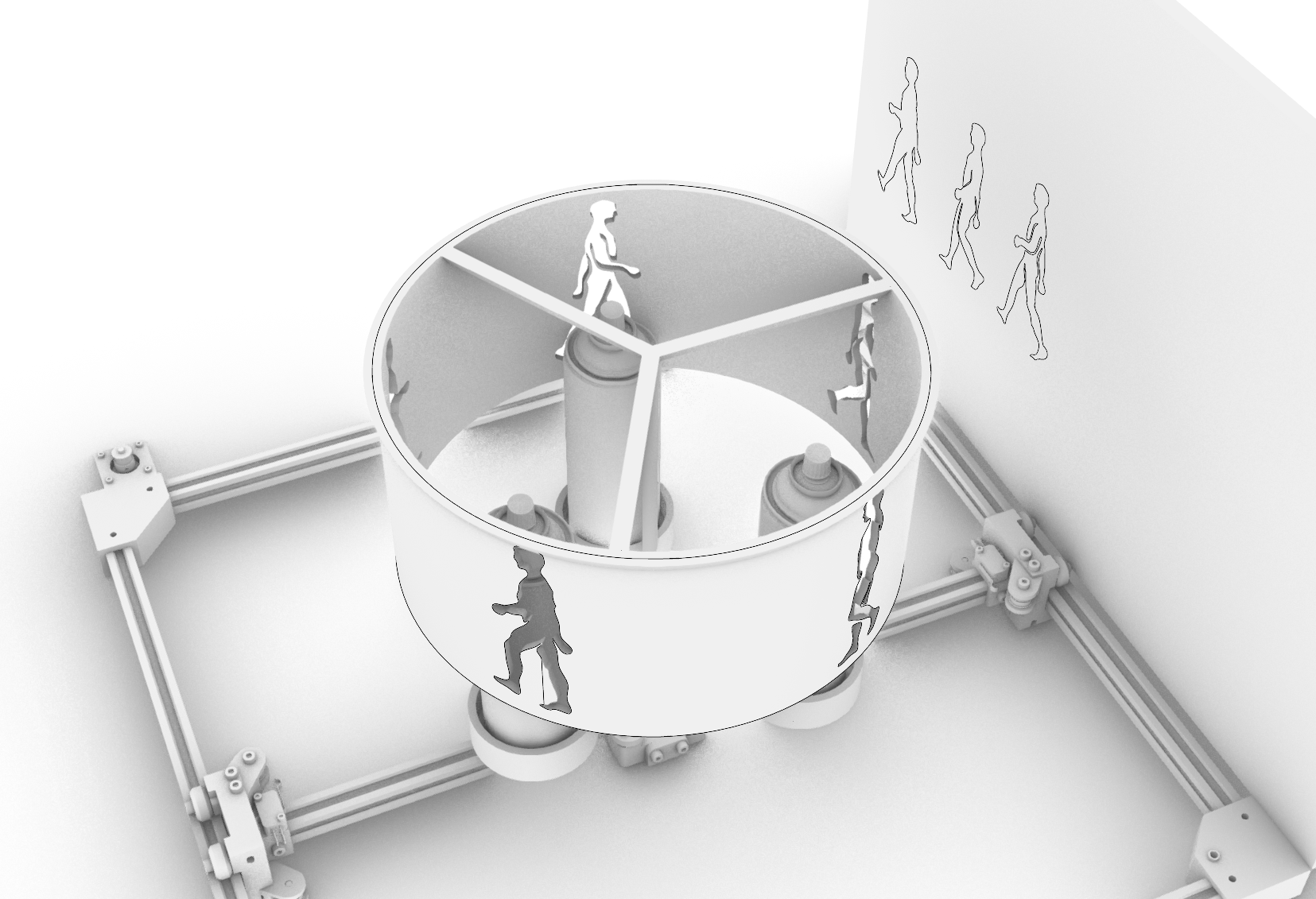
The final design focuses not only on the spray can machine but also on the canvas itself. While the spray can remains stationary and the zoetrope element rotates, other components enrich the narrative of the painting in sequence. The canvas is in constant movement, allowing the stencil figures to create layered patterns. Over time, these repeating and evolving patterns build a visual story, transforming motion and color into a dynamic narrative. This interplay between rotating elements, moving canvas, and stenciled figures turns the painting into an expressive, evolving storytelling tool.
Production
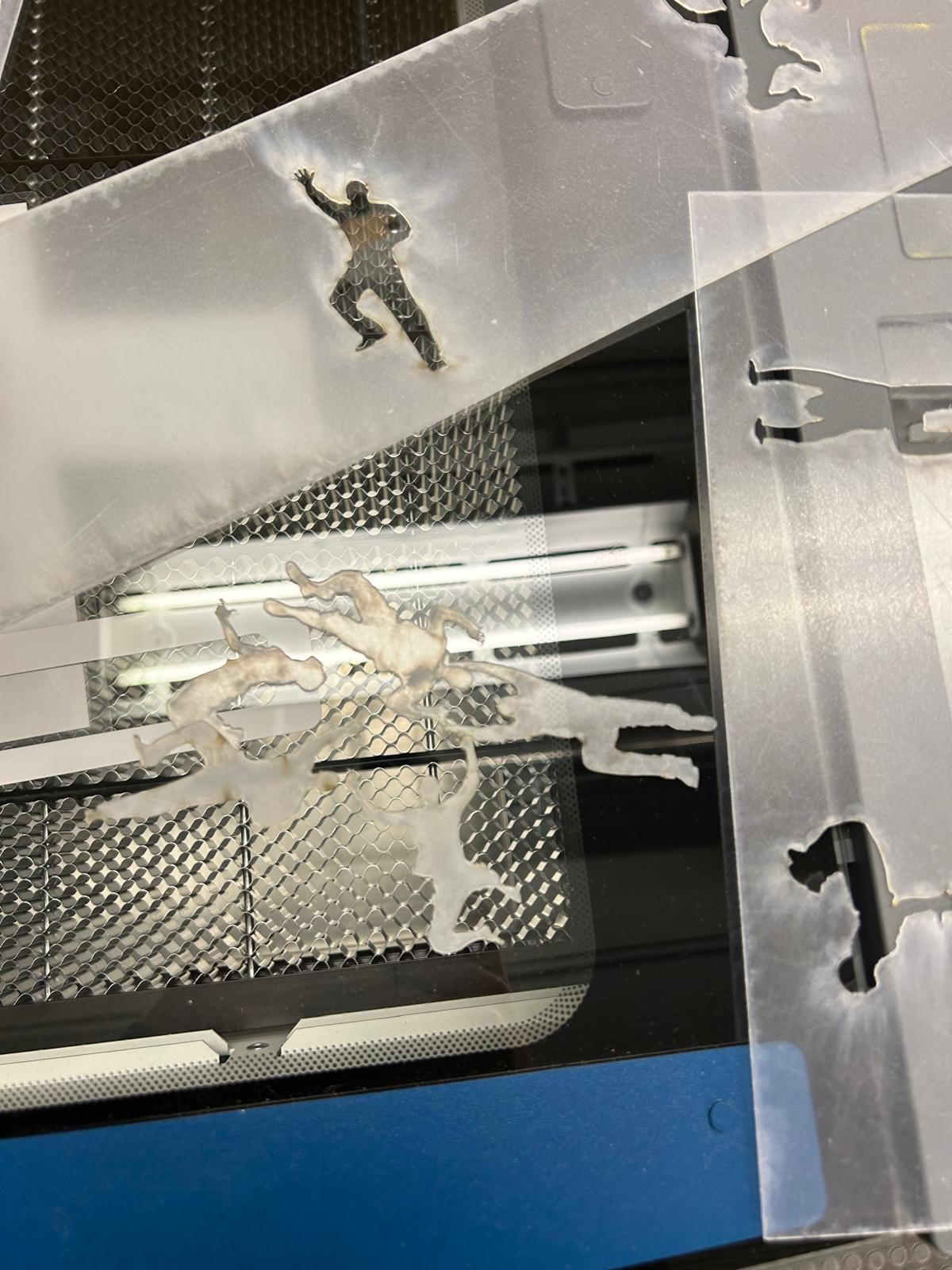
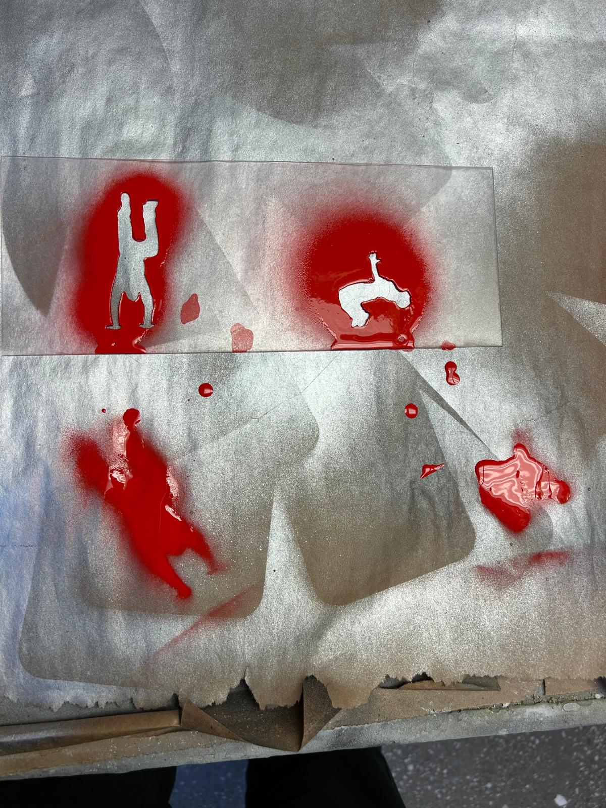
After all my parts were 3D printed and the servos were fitted into their designed positions, I had to laser-cut the figures for the stencils. I used photoshop and rhino 8 to prepare the file. The material that I used is called PETG plastic, which is suitable for laser cutting. Since there were no instructions regarding the power or speed settings for the laser, I performed several quick test runs to determine the optimal settings.

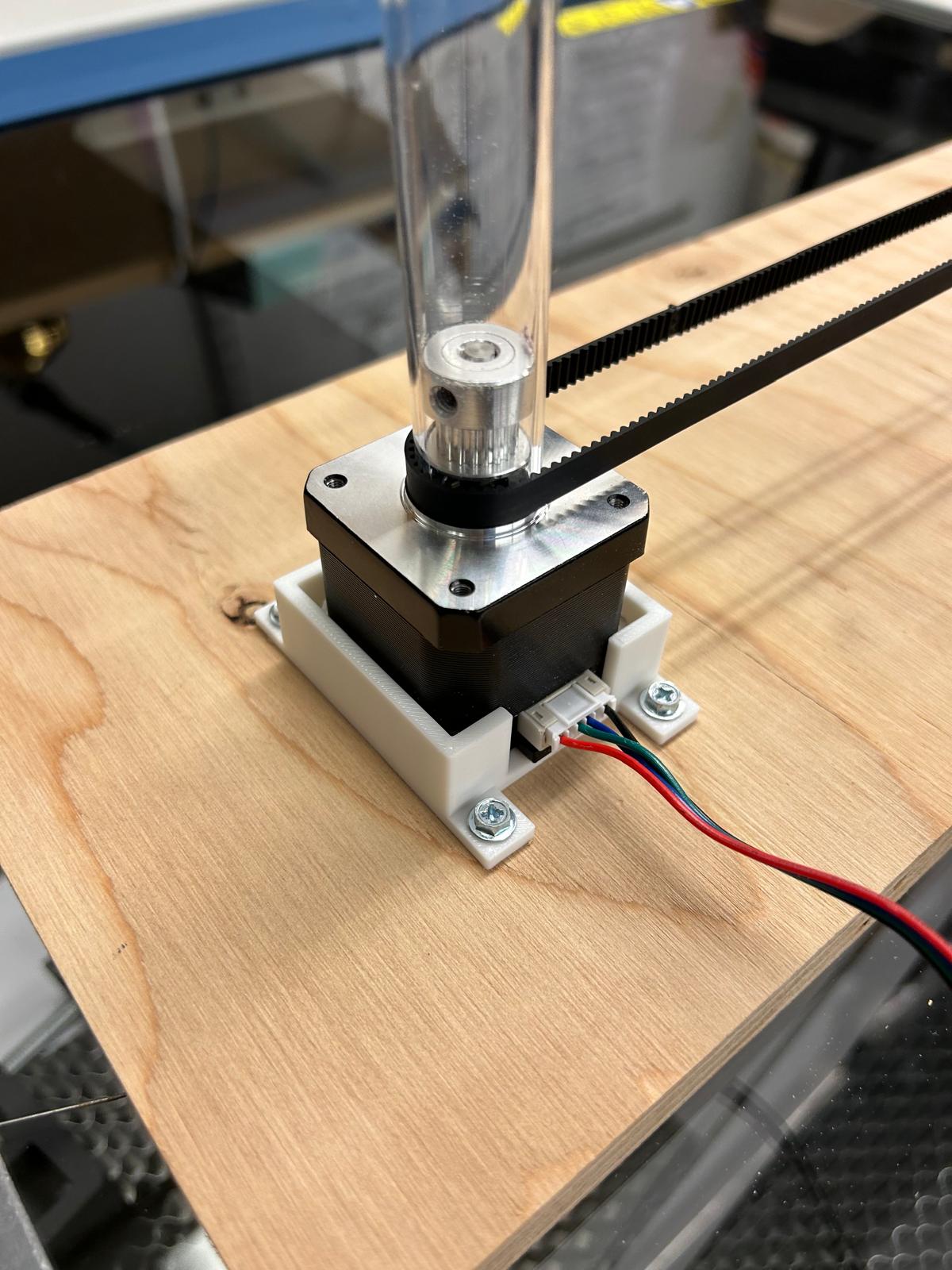
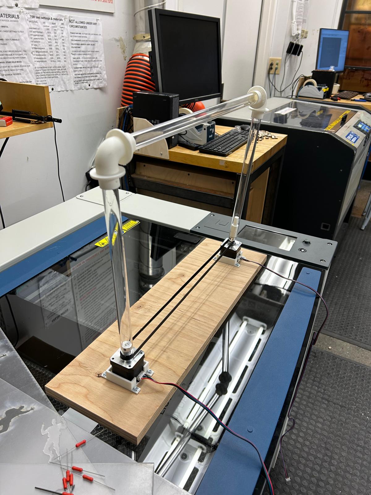
The final step in assembling the project was constructing the canvas. I began by preparing the frame using PVC tubes, which I cut to size with a bandsaw to create a stable structure. To secure the stepper motors in their positions, I 3D-printed custom bases and attached them firmly to a wooden surface with screws, ensuring both stability and precise alignment. For the painting surface itself, I used a piece of fabric I had on hand, chosen because its texture closely resembled that of a traditional canvas. This fabric was stretched and mounted over the frame, providing a suitable surface for the stencils and spray mechanism. With the frame, motors, and painting surface assembled, the system was fully prepared for testing and artistic operation.

Electonics
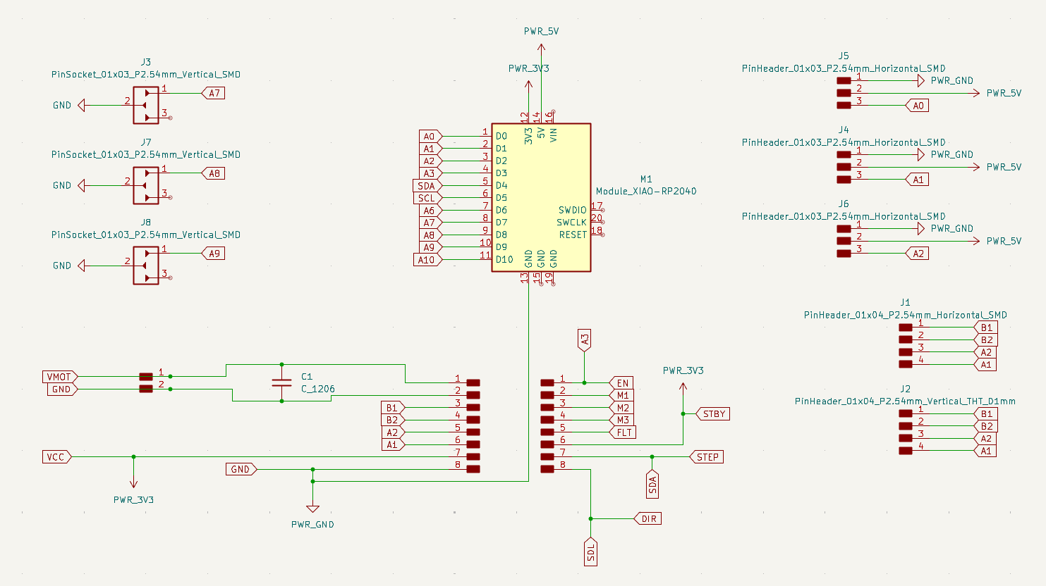
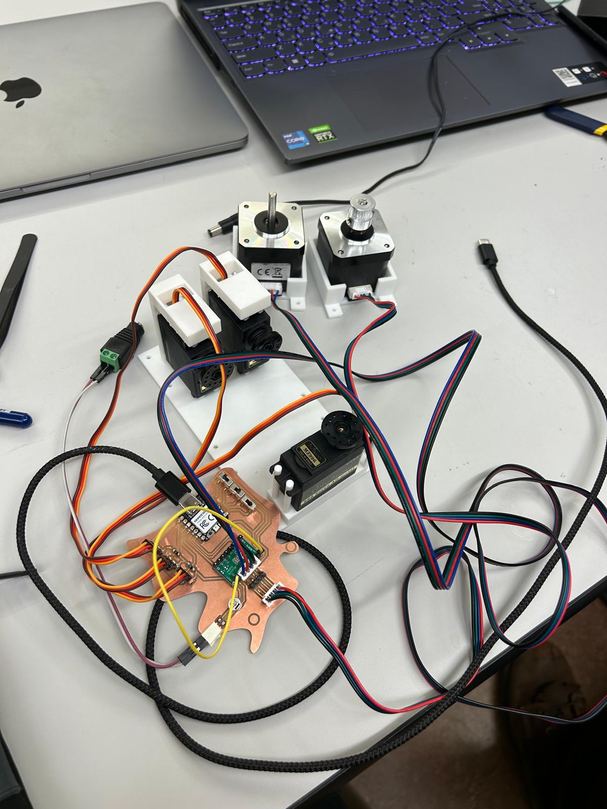
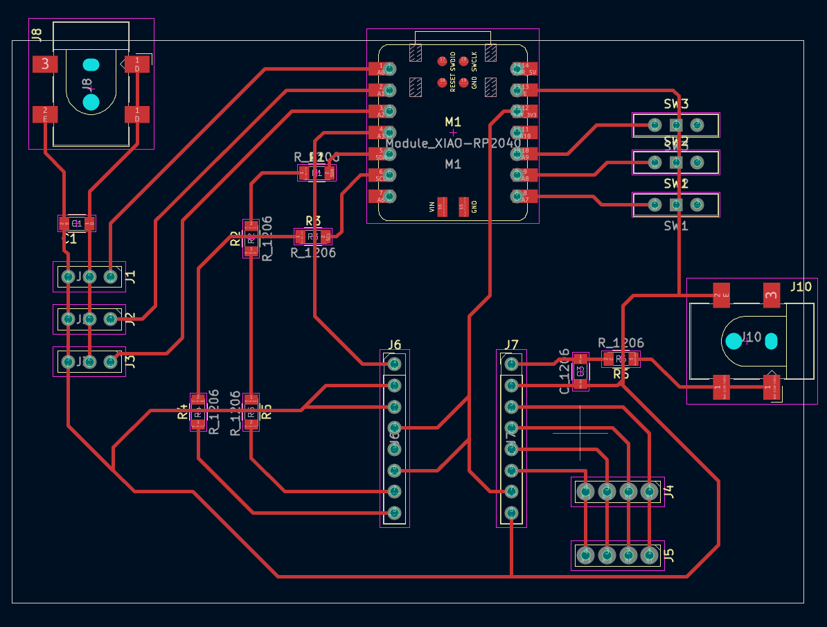
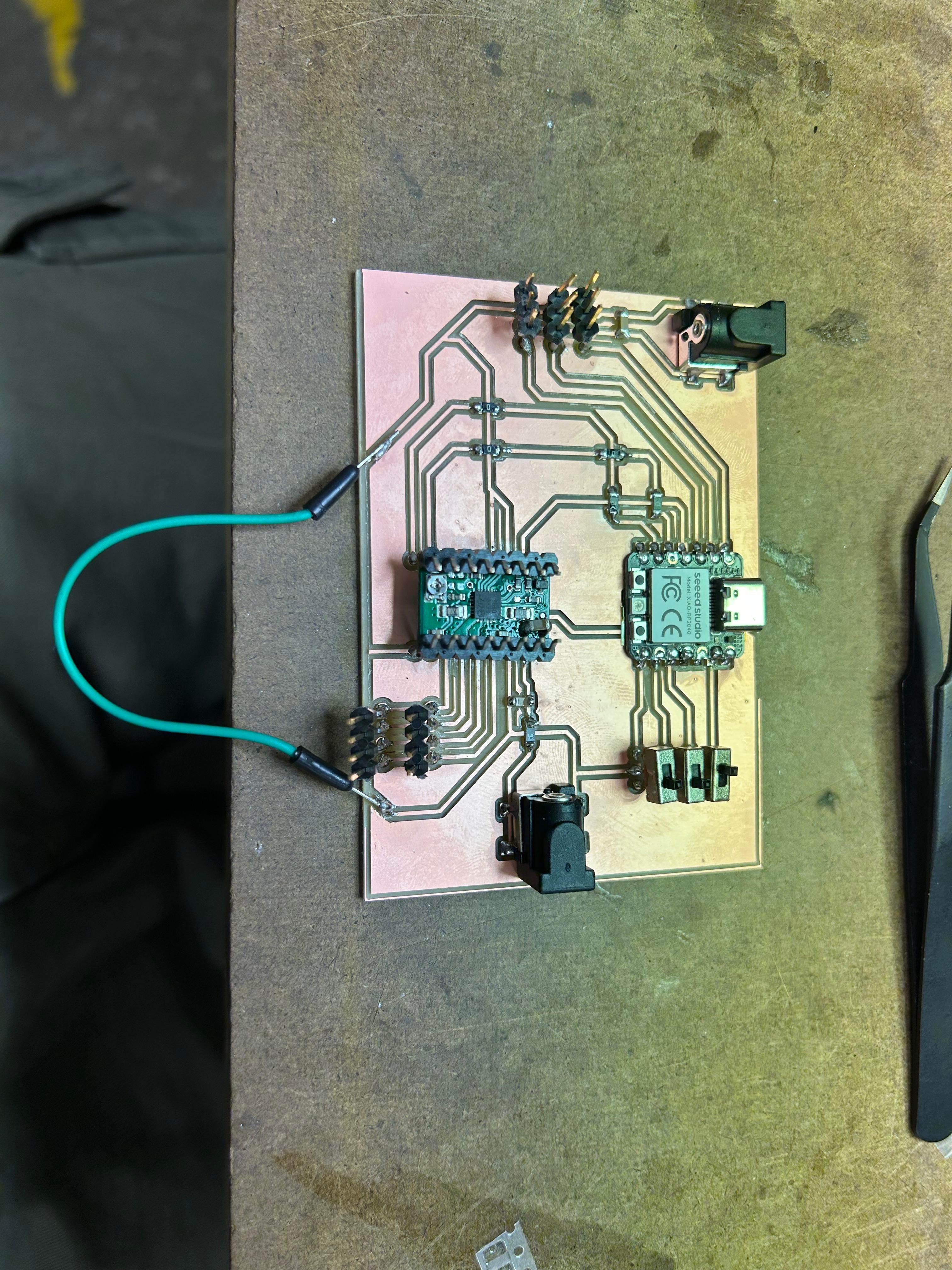
For my circuit board design, I used the Seeed XIAO RP2040 microcontroller as the main control unit. It provides PWM signals to three MG996 servo motors, which are powered directly by an external 5 V, 3 A supply. Each servo’s signal line is connected to a separate PWM pin on the RP2040. All grounds—including the RP2040, the servos, and the stepper driver—are connected together to form a common ground, ensuring stable operation.
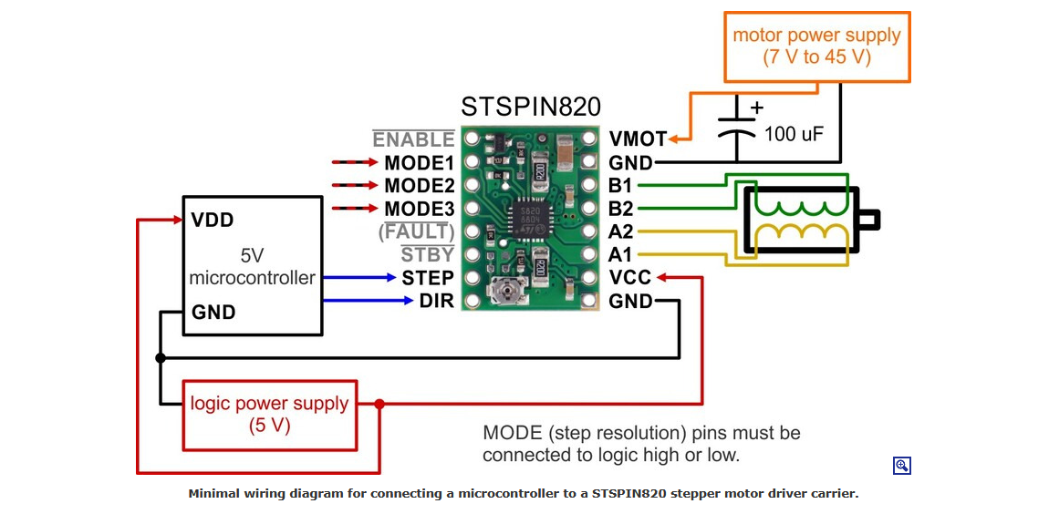
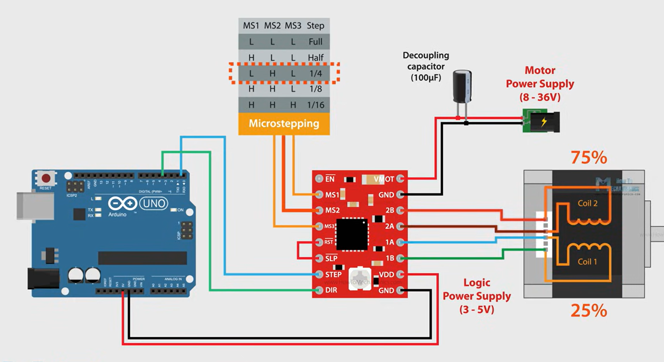
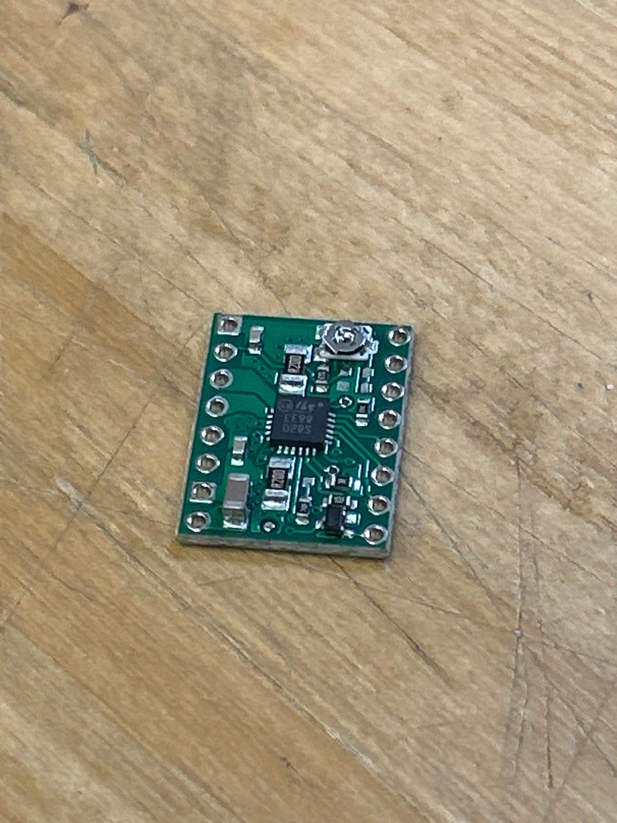
The design also includes two 17HS1504S-X1 NEMA 17 stepper motors, controlled by a single STSPIN820 driver. The driver receives 12 V from the external supply at the VMOT pin. A decoupling capacitor is placed across VMOT and GND to reduce voltage spikes and improve stability. Control signals (STEP, DIR, EN) are connected from the RP2040 to the driver, while the driver’s GND is tied to the common ground.The circuit includes three switches as user inputs, each connected to a digital pin on the RP2040 with pull-up or pull-down resistors. The RP2040 is powered through its USB connection to a computer, providing stable logic power without relying on the external supply.
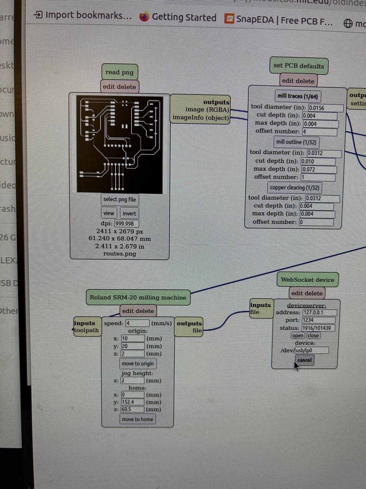
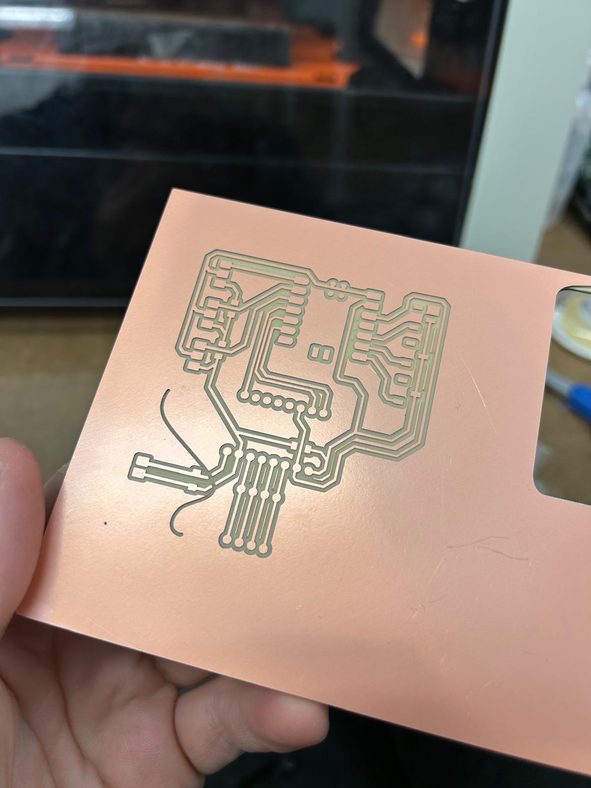
takeout
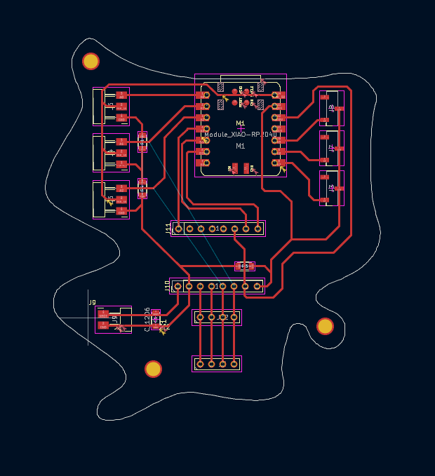
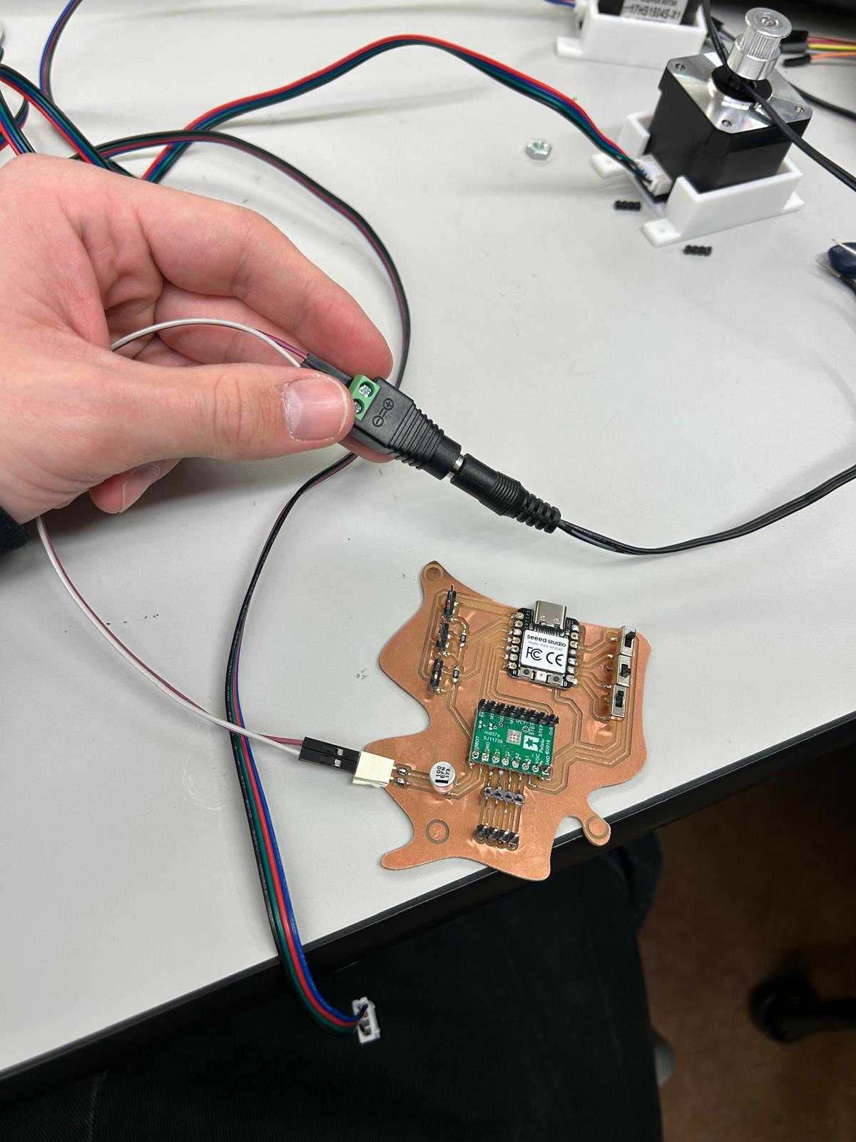
For the past few days after the presentation I ended up working on my pcb and trying to figure out what didn't work. I designed a new board paying attention to things that maybe I neglected in the first iteration.What I changed is that I added decoupling capacitors for the servos, I made sure that all the grounds were connected properly and I addeda separate power supply for the servos. I also added a capacitor for the stepper motor driver to make sure that there are no voltage spikes.
through this project I learned how to combine mechanical design, electronics, and programming to create an interactive art installation.During testing, my electric circuit did not function as expected, and several factors likely contributed to the issues. First, the servo motors were initially considered to be powered from the RP2040’s 5 V output, which is insufficient. Each MG996 servo can draw up to 2–3 A at peak, whereas the microcontroller’s 5 V pin or USB port can supply only a few hundred milliamps. This voltage drop caused the servos to jitter, stall, or fail to respond, preventing proper operation. Second, the stepper motors were driven by a single STSPIN820 driver, which is acceptable only if both motors move identically. Differences in mechanical load or wiring could cause uneven movement or missed steps. Additionally, the lack of a decoupling capacitor across the driver’s VMOT and GND may have led to voltage spikes during stepper operation, destabilizing the
microcontroller or motors.